
Nicole R. Lucas
Structural Option
Franklin Square Hospital
Patient Tower Addition
Baltimore, MD
| HOME |
| STUDENT BIO |
| BUILDING STATISTICS |
| THESIS ABSTRACT |
| TECHNICAL ASSIGNMENTS |
| THESIS RESEARCH |
| THESIS PROPOSAL |
| PRESENTATION |
| FINAL REPORT |
| REFLECTION |
| E-STUDIO HOMEPAGE |
“Note: While great efforts have been taken to provide accurate and complete information on the pages of CPEP, please be aware that the information contained herewith is considered a work‐in‐progress for this thesis project. Modifications and changes related to the original building designs and construction methodologies for this senior thesis project are solely the interpretation of Nicole Lucas. Changes and discrepancies in no way imply that the original design contained errors or was flawed. Differing assumptions, code references, requirements, and methodologies have been incorporated into this thesis project; therefore, investigation results may vary from the original design.”
Building name: Franklin Square Hospital Center
Location and site: 9000 Franklin Square Drive, Baltimore, MD 21237
Building Occupant Name: Lillbridge Franklin Square
Occupancy or function types: Hospital
Size: 356,000 square feet
Number of stories above grade/total levels: 7 stories adding up to 105 ft to top of penthouse roof slab.
Primary project team:
Owner |
Franklin Square Hospital Center |
|
Architect |
Wilmot/Sanz Inc. |
|
MEP Engineer |
Leach Wallace Associates |
|
Structural Engineer |
Rathgeber/Goss Associates |
|
Civil Engineer |
Dewberry and Davis |
|
Construction Manager |
Bovis Lend Lease |
Dates of construction:
The construction of the tower started in November 2007. Construction is scheduled to be completed in 2010. June 2010 (first turnover) October 2010 (last turnover)
Actual Cost Information:
The projected cost of the tower addition only is $119 million. The central energy plant, sitework, and interior renovations are an additional $16 million.
Project delivery method: CM @ Risk
Architecture:
Franklin Square hospital was founded in 1898. Now Franklin Square is the third largest hospital in Maryland, making it one of the largest employers in Baltimore County with the busiest emergency department in the state. The seven story 356,000 square foot patient tower addition includes an expanded six zone emergency department with 70 treatment areas, 291 private inpatient rooms, an ICU including 42 beds, and four new medical/surgical units. The new additional includes a peaceful environment designed to decrease the noise and crowding usually found in hospitals causing anxiety for patients.
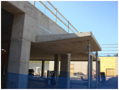
The first two stories and the penthouse level of the patient tower consist of exposed concrete pre-cast panels with a 2’ concrete trim at each floor line. The remaining stories consist of pre-cast panels with brick veneer and a 2’ concrete trim at floor line. The typical window is an aluminum curtainwall system that is 6’x5.5’. Featured on the south side of the building is a 2 story atrium with an aluminum curtainwall system.
Codes:
International Building Code 2006, Life Safety Code 2006, International Fire Code 2006, AIA Guidelines for Hospital and Health Care Facilities 2006, National Electrical Code 2005, International Mechanical Code 2006, National Standard Plumbing code 2003 with 2004 Supplement, International Energy Code 2006
Zoning:
Franklin Square Hospital is located in zoning ordinance D.R. 5.5 of Baltimore County. The hospital also falls under the Intuitional Title 7 of the zoning code.
Building Envelope:
The building is covered with a series of pre-cast panels. The panels is a system with a 7 ½” thick precast concrete panel with a 2” cavity, 6” metal stud framing with 6” thermal insulation, vapor barrier and 5/8” gypsum wall board. The remaining façade is a 2 ½” x 6” aluminum curtain wall system. The atrium is accentuated with a ½” thick tempered decorative glass panels including hardwood guard rails.
The main roof system is a 1.5” deep, wide rib, 20 gage galvanized metal deck. The deck is covered with tapered rigid insulation and a HPR modified roofing membrane. The penthouse system consists of a structural slab 3 ¼” lightweight concrete over 2” deep x 18 gage galvanized composite metal deck reinforced with 6x6-21.4x1.4 WWF. The deck is covered with rigid insulation and a roofing membrane.
Structural System:
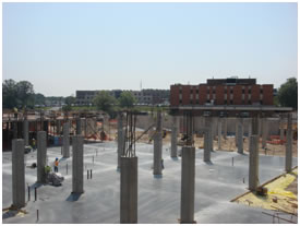
The foundation system of the new Franklin Square Hospital Patient Tower consists of drilled piers or caissons 4’ in diameter centered under columns with grade beams sitting on top of the piers. The top of the pier elevations are -2’-0” for the interior columns and -5’-0” for the exterior columns with grade beams with all of them extending to -42’-0”. The size of a typical grade beam is 24”x24” with a few that are 36”x24”. There are spread footings under the canopy. These footings are 5’x5’x14” supporting HSS10x.375 and 2-5’x8’x20” supporting 18”x24” concrete columns. An existing retaining wall will be used on the plan north side of the footprint. A 12” foundation wall will be constructed around the perimeter. The elevator pit is supported by a 12” thick wall that is 5’-0” high. The Patient Tower utilizes a 5” slab on grade.
The typical floor system is a 10” concrete slab. There are a series of concrete beams along the perimeter and encasing the stairs and elevators. The typical span is 30’x30’ with 15’ spans around the elevators and stairs. The typical reinforced column size is 22x22 or 21x21 carrying up to the main roof on the seventh floor. There are also columns sized for a future expansion of part of the footprint. Multiple beams require a camber for deflection purposes.
Franklin Square Hospital Patient Tower utilizes the entire structure to resist lateral forces. Therefore every column/slab connection is an ordinary reinforced concrete moment frame.
The main roof system consists of W12x16 beams spanning 20’, W12x14 spanning 15’ and W14x22 spanning 30’. All beams are spaced at 5’ and frame into W16x40, W21x73 and W18x50 girders that span 30’. The roof deck is 1.5” deep, wide rib, 20 gage galvanized metal deck.
Construction:
The CM on Franklin Square Hospital is Bovis Lend Lease. There is a CM at risk delivery process. Construction started in November of 2007 and final turnover is expected to be in October of 2010. Since this patient tower is an addition to the existing hospital, the construction of the new tower includes connecting to an existing building on each floor up to and including the third floor.
Transportation:
The new patient tower includes two service elevators and two public elevators. The two public elevators extend to the sixth floor, while the service elevators transport to the penthouse. Also included in the plans are two future elevators; one service and one public. There are 3 sets of stairs one on each plan north and plan south of the building and another set of stairs located by the elevators.
Lighting/Electrical:
Most lighting in the hospital consists of 2’x2’, 1’x4’ and 2’x4’ florescent lights for the offices and patient rooms. Parabolic louvers are used in offices. Recessed lighting is used in the waiting areas. There is a multitude of ceiling mounted exam lights. A series of wall mounted night light fixtures are included in all patient rooms and adjoining restrooms including industrial and fluorescent lighting. The exam portion of patient room lighting fixtures can be controlled by a switch that is installed in a console unit. Ambient and reading portion of lighting are controlled by the nurse call pillow speaker. The atmosphere in the atrium is created with round lighting fixtures and floor mounted bollard fluorescent lighting fixtures controlled by ceiling mounted photo sensors. There are also series of exit lights. Several outdoor lights are used to accentuate the façade.
The power supplied to the patient tower is a 480Y/277V including powering the lighted signage mounted on the canopy which reduces down to a 208Y/120V for lighting and receptacles by a series of 15 transformers each with a capacity of 150kVA. This is a 3 phase, 4 wire system. An emergency circuit is included all throughout the building. The ICU runs on a 3 phase, 5 wire system. The 3 phase, 4 wire system is transformed to a 3 phase, 5 wire system through 3 phase dry transformers. External low voltage sequential relay systems are used to control lighting fixtures in the ICU by the pillow speaker and a wall switch. Panel rooms are located on each floor along with usage of existing panel boards on the first floor.
A run of ¾” conduit will be installed through the ceilings for security and other systems.
Fire Protection:
The patient tower is fully sprinklers with a dry-pipe sprinkler system, low air, water flow and valve tamper, pre-action system. The fire alarm system is connected to the existing system. There are several fire alarm addressable monitor modules connected to booster panels; one per circuit and an amplifier panel that serves all floors from the ground level. There are also a series of detectors in the ducts to control the dampers in case of a fire. Smoke detectors are installed throughout the building including stairways to initiate pressurization fans. Smoke control panels are used in the atrium and stairwells for the exhaust fans. Most of the new construction has a 2-hour rating.
Mechanical System:
The floor plans are broken up into heating zones ranging from 4-9 zones per floor. Franklin Square has a separate central plant system on site. The plant includes two three-ton unitary Trane cell cross flow cooling towers and two Marley electric centrifugal chillers. They work together to serve #9 and #10 AHU. These air handling units are pre-filter 100% economizer backwards incline tanks. Altogether there are 11 air handling units serving the patient tower addition. The system runs at variable percentages of outdoor air, ranging from 10%-50%. There are 2 mechanical shafts located in the middle of the floor plans. The stairwells and lobby are served by unit heaters. The air is a combination CV, VAV, CAV system. Included are two fuel oil tank boilers on site.
Franklin Square includes an automatic temperature control throughout most of the building. For some of the special areas, there is an isolation exhaust air system. There are room pressurization monitors for isolated room control.
Lightning Protection System:
Lightning protection air terminals and wiring for a completely new system are installed in accordance with NFPA 780 and UL 96A. These are bounded to steel framing to the ground termination rod. The ground rods are 5’-0” from the edge of roof.
Telecommunications:
Installed in each patient room and waiting room are cable television outlets. Also, each patient room is connected to a nurse call system.
For security purposes, magnetic door locks and card readers are installed. Access control includes a 4”x4” junction box and vertical device ring at each location. The security system is run through 2” conduit.
All conference rooms include audiovisual signal for presentation and communication purposes.
|
||

The Capstone Project Electronic Portfolio (CPEP) is a web‐based project and information center. It contains material produced for a year‐long Senior Thesis class. Its purpose, in addition to providing central storage of individual assignments, is to foster communication and collaboration between student, faculty consultant, course instructors, and industry consultants. This website is dedicated to the research and analysis conducted via guidelines provided by the Department of Architectural Engineering. For an explanation of this capstone design course and its requirements click here.